Building a 3-Axis Camera Gimbal with STM32 and SimpleFOC
March 1, 2026
Tags: stm32 gimbal bldc pid imu embedded pyqt python
So I built a camera gimbal. Not just the mechanical part, but the firmware, the sensor fusion, the PID loops, everything. I also ended up building a whole desktop app for PID tuning, real-time visualization, joystick control.
It only stabilizes on two axes right now (pitch and roll) because the motor magnets are messing with the magnetometer on the ICM20948. Yaw is wired up and the code is there, but the mag readings are garbage at this distance from the motors. Redesigning the frame is on the list.
Anyway, here’s it working:
The Hardware
The MCU is an STM32F401CC Black Pill. 84 MHz Cortex-M4, cheap, has enough pins. I program it with an ST-Link through PlatformIO.
For the IMU I’m using an ICM20948. It’s a 9-DOF sensor (accel, gyro, magnetometer), but like I said, I’m only running 6-DOF right now. The mag calibration code is all there (hard-iron, soft-iron, the works) but the 2805 motor magnets are just too close and overpower the Earth’s field completely. I need to rethink the physical layout.
The motors are 2805 140KV gimbal brushless motors, 7 pole pairs. Low KV so they move slowly and smoothly, which is what you want for this. Each one is driven by a SimpleFOCMini board. No encoders or hall sensors, just open-loop angle control through the SimpleFOC library. Sounds like it shouldn’t work but it does.
Pin mapping:
| Axis | Phase A | Phase B | Phase C | Enable |
|---|---|---|---|---|
| Roll | PA0 | PA1 | PA2 | PA4 |
| Yaw | PA10 | PA8 | PA9 | PA4 |
| Pitch | PB1 | PB0 | PA7 | PA4 |
IMU is on I2C, PB6/PB7, 400 kHz.
Firmware Architecture
C++ with Arduino framework, all through PlatformIO. The structure looks roughly like this:
graph TD
    Main["main.cpp"] --> Gimbal
    Gimbal --> IMU
    Gimbal --> RollMotor["Motor (Roll)"]
    Gimbal --> YawMotor["Motor (Yaw)"]
    Gimbal --> PitchMotor["Motor (Pitch)"]
    Gimbal --> RollPID["PID (Roll)"]
    Gimbal --> YawPID["PID (Yaw)"]
    Gimbal --> PitchPID["PID (Pitch)"]
    Main --> Parser["Parser (Serial)"]
    IMU --> Madgwick["Madgwick AHRS"]
    IMU --> ICM["ICM20948 Driver"]
    RollMotor --> FOC["SimpleFOC"]
    YawMotor --> FOC
    PitchMotor --> FOC
Gimbal does most of the work. Reads the IMU, runs stabilization, moves the motors, sends telemetry. Parser deals with serial commands coming from the PC.
The main loop is literally just:
That’s it.
Sensor Fusion
This part took me the longest to get right.
graph LR
    Raw["Raw Accel + Gyro"] --> Calib["Offset Calibration"]
    Calib --> Remap["Axis Remapping"]
    Remap --> Madgwick["Madgwick Filter (400 Hz)"]
    Madgwick --> Quat["Quaternion"]
At startup, the IMU collects 2000 samples to figure out gyro and accelerometer offsets.
The ICM20948 axes don’t match my gimbal frame at all. Here’s how they’re oriented from the datasheet:
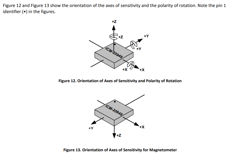
So in firmware I had to remap them to match my gimbal’s frame:
| Gimbal Axis | Accel/Gyro Source | Mag Source |
|---|---|---|
| X | Z | -Z |
| Y | Y | -Y |
| Z | -X | X |
I got this wrong a few times and the gimbal would just fight itself, pitch corrections going to roll and vice versa. Took me a while to figure out what was happening.
For the actual sensor fusion I’m using the Madgwick filter, running at 400 Hz. It takes the raw accel and gyro data and gives back a quaternion. There’s a beta parameter that controls the tradeoff between convergence speed and noise. I’m still not 100% sure I have the best value for it, I just kept trying numbers until it felt stable enough.
Quaternions and PID
So originally I was using Euler angles with a complementary filter. Seemed straightforward enough: blend gyro and accel, get roll/pitch/yaw, throw a PID on each one. And it kind of worked, for small angles. But then I’d tilt past about 90 degrees pitch and everything would go crazy. Gimbal lock. The angles would jump around and the axes would basically swap meaning. Classic Euler angle problems that I really should have expected but didn’t.
Switched to quaternions after that. Took me a while to actually understand the math. But once I got the quaternion error approach working, the improvement was immediately obvious. No more singularities, no more random jumps.
The stabilization runs at 40 Hz (every 25 ms):
graph TD
    QCurrent["Current Orientation (quaternion)"] --> QError
    QDesired["Desired Orientation (quaternion)"] --> QError
    QError["q_err = q_desired * inverse(q_current)"] --> RotVec["Extract Rotation Vector (rx, ry, rz)"]
    RotVec --> AddTarget["Add Target Offsets"]
    AddTarget --> PIDRoll["Roll PID"]
    AddTarget --> PIDPitch["Pitch PID"]
    AddTarget --> PIDYaw["Yaw PID"]
    PIDRoll --> MotorRoll["Roll Motor Angle"]
    PIDPitch --> MotorPitch["Pitch Motor Angle"]
    PIDYaw --> MotorYaw["Yaw Motor Angle"]
Basically you take where the gimbal is, take where it should be, compute the quaternion error between them, turn that into a rotation vector (three floats, one per axis), and feed each one into its own PID. The PID output goes straight to the motor.
I added anti-windup on the integral term after the gimbal did a full 360 on me a couple times. That was fun.
The gains I ended up with:
| Axis | Kp | Ki | Kd |
|---|---|---|---|
| Roll | 0.05 | 5.0 | 0.0 |
| Pitch | -0.15 | -7.5 | 0.0 |
| Yaw | 0.0 | 0.0 | 0.0 |
No D term. I tried adding one but it didn’t really do anything useful here. Pitch gains are negative because of how the motor is mounted. These values came from a lot of trial and error in the desktop app, which I’ll get to. One thing is that the Black Pill doesn’t have EEPROM, so there’s no way to persist PID gains on the board. I can tweak them live from the desktop app, but once I power cycle the gimbal it goes back to whatever’s hardcoded in firmware. So once I’m done with tuning, I have to update the defaults in code and reflash.
Since the motors are open-loop with no encoders, they just go to whatever angle you tell them. If something blocks them physically, they have no idea. But for a camera gimbal the loads are tiny, so it hasn’t been a problem.
Serial Protocol
I needed the firmware and PC to talk to each other. Went with a binary protocol instead of text because I didn’t want to deal with parsing floats from strings and losing precision. Binary is also way more efficient over UART since the packets are smaller and there are no delimiters to worry about.
The packet format:
| Field | Size | Description |
|---|---|---|
| Preamble | 1 byte | $ (0x24) |
| Size | 4 bytes | Payload length (little-endian) |
| Command | 1 byte | Command ID |
| Payload | N bytes | Command-specific data |
Parser is a simple state machine: PREAMBLE → SIZE → CMD → PAYLOAD. Same protocol on both sides (firmware in C++, PC in Python), both use registerAction(cmd, handler) to dispatch packets.
Commands:
| Cmd | Name | Direction | What it carries |
|---|---|---|---|
| 0 | Log | Firmware → PC | Debug strings |
| 3 | Telemetry | Firmware → PC | 3 floats (pitch, roll, yaw angles) |
| 4 | PID Data | Firmware → PC | 6 floats (angle + setpoint per axis) |
| 5 | Set PID | PC → Firmware | Axis char + 3 floats (P, I, D) |
| 6 | Read PID | Firmware → PC | 9 floats (all gains) |
| 10 | Send Targets | PC → Firmware | 3 floats (pitch, roll, yaw) |
Telemetry comes in at 5 Hz. Fast enough to plot, slow enough to not flood things.
GimbalConsole
I got tired of not being able to see what the gimbal was doing in real time. A serial terminal wasn’t going to cut it for tuning PIDs. So I wrote a desktop app in PyQt5.
graph TD
    MainWindow --> SerialManager["Serial Manager"]
    MainWindow --> ControlPage
    MainWindow --> PIDPage["PID Page"]
    MainWindow --> LogPage["Log Page"]
    SerialManager -->|"Binary Packets"| Firmware["Gimbal Firmware"]
    ControlPage --> Joystick
    ControlPage --> Plotter["Realtime Plotter"]
    ControlPage --> Keyframe["Keyframe Editor"]
    PIDPage --> PIDInputs["PID Gain Inputs"]
    PIDPage --> PIDPlots["Angle vs Setpoint Plots"]
It uses qdarkstyle for the dark theme and pyqtgraph for the plots. Serial communication runs on a background thread using the same binary protocol as the firmware.
Control Page
Three things here. A virtual joystick I made where mouse position controls pitch/roll and scroll wheel does yaw. A realtime plotter that shows the angle telemetry streaming in. And a keyframe editor, which I’ll talk about in a sec.
PID Tuning
This page is where I spent most of my time honestly. You can set P, I, D gains and a trim offset for each axis, and there are live plots showing the actual angle vs the setpoint. Being able to see overshoot and oscillation in real time while adjusting gains made tuning so much faster than doing it blind. I’d just sit there tweaking Ki on the pitch axis and watching the plot until it stopped oscillating.
Keyframe Animation
I wanted to script camera movements. Like, define “at t=0 be at 0 degrees, at t=3 be at 45 degrees, at t=5 come back” and have the gimbal follow that path smoothly.
So the keyframe editor lets you click on a plot to add keyframes for each axis, pick an interpolation method (PCHIP, Akima, Cubic, or Linear, all from scipy), hit play, and the gimbal follows along. There’s a speed control too.
PCHIP ended up being the most useful because it doesn’t overshoot. Cubic splines would sometimes swing past the target angle which looked weird. Akima is good too if you have enough points.
Here it is in action:
Wrapping Up
This whole project was basically me learning a bunch of stuff I didn’t know before. Sensor fusion, quaternion math, PID tuning, real-time embedded stuff. The firmware runs the Madgwick filter at 400 Hz and stabilization at 40 Hz.
Next up is redesigning the frame so the motors are further from the IMU. Once the magnetometer actually works, I can get yaw stabilization going and have all three axes running.
If you want to check out the code, both repos are on GitHub: BlackPillGimbal for the firmware and GimbalConsole for the desktop app.
It’s definitely not perfect. But building it forced me to actually understand all the pieces. Euler angle singularities sent me down the quaternion rabbit hole. Axis remapping had me questioning my sanity for a week. Integral windup made the gimbal spin in circles. And the motor magnets are still ruining my mag readings. But yeah, that’s the fun of it.